Introduction
I would like to tell the story of a project I undertook during my first years at university. Back then, I was traveling through Europe in summer and visited the country I am originally from, Belarus. I was meeting several friends from my past and revisiting some childhood memories. One evening, just before I was about to leave for home, my former classmate stopped me. He asked whether I could spend some time looking for quadriplegic patient rehabilitation programs in Germany. Someone from the school we both attended had had an accident and ended up in a wheelchair. While the search for rehabilitation is a different story, let me tell you what this occasion inspired me to do.
After returning to Germany, on one of the weekends, I encountered a Hackaday article announcing a Mobility Unlimited Challenge organized by Toyota Mobility Foundation. The picture speaks for itself; the topic was mobility for impaired people. The application deadline was in two months, so I had a chance to apply with an idea I had been thinking about since I was struck by the news about our quadriplegic acquaintance.

The idea I had was very simple. Imagining what type of obstacles a person in a wheelchair would encounter in a country like Belarus, I thought that stairs, curbs, ramps, and the like are limiting the quality of everyday life. While some countries already build or reconstruct for people with various grades of mobility, most of the post-Soviet countries are hardly suitable for comfortable living if one is impaired. While adjusting the infrastructure is inevitable at some point, the easiest support to apply locally would be to adapt the wheelchair. I thought it would be great to have as little change as possible, keeping the main wheelchair frame as is, but coming up with a wheel design that would be adaptable to the environment.
The idea
And here it is: the idea was to make wheels that would balance when needed. Since the wheels would be powered, they could easily provide push support if needed, for example on ramps or hills. Additionally, if you've ever seen how wheelchair users tackle curbs, you'd realize they balance on the main wheels all the time. After talking to some users, I also learned that not everyone is comfortable balancing, so this support would be great to have. By the way, I tried to balance and to fall backwards and generally to go around in a wheelchair for a bit; it helps a lot in imagining what it might feel like.
A good friend of mine helped me to quickly design a model frame to visualize the concept. I later 3D printed it in a local makerspace at my university and attached the frame to two BLDC motors I had lying around from one of my past projects. I programmed a very basic PID control with accelerometer and gyro feedback. Terribly tuned, on one of the long nights it started balancing, which made me super happy and was enough to show in the application.


I would like to say thank you to Erik, a good friend of a friend in Dresden, who is actually a wheelchair user. He helped a lot with feedback and took part in some video making for the application to the Mobility Unlimited Challenge.
I didn't have many expectations, since I was applying as a solo, non-commercial applicant. But on one of the days in March, I heard back from Toyota with confirmation that I had received the 50k USD grant to continue building this project!
First steps
The next weeks were quite busy. I started by registering a legal entity to keep the money flow smooth, and also started hiring on campus for working students. The challenge consisted of several stages, and at every stage, you could compete for a monetary grant to continue building the product. I only had 4 months from then to build something for the jury panel and convince them of the project's viability. The project got a name - aesthel.

TU Dresden supported my initiative by providing us with a shipping container. These are reserved for student start-ups, and it seems we were eligible.

We had some furniture, whiteboards, and a whole window - what else do you need? I bought some equipment and office supplies, and we were good to go. Here are some memories from those weeks.


I say "we" since the team grew to 3 people. I was joined by Patrick and Leon, who were responsible for mechanics and software. We spent a lot of time in this container drinking tea :) Leon is on the left-hand side, and Patrick is on the right-hand side.

Technical details
I found a picture of a whiteboard from back then. It shows some technical details. The powertrain is simple - we got 8 cells of LiFePO4 rechargeable batteries giving us 12Ah with probably like 2C or 3C peak current to the motor drivers. In the diagram, there is an STMicroelectronics IHM08M1 BLDC driver planned. In fact, we reached out to Trinamic. Back then it was a proper German company, not yet acquired by Analog Devices. Trinamic was super friendly to students and supported us with various motor drivers to test, including all the knowledge base we needed. If I remember correctly, the driver we ended up using was TMCC160, a fully integrated Field Oriented Control module with position feedback. We included some IMUs for orientation feedback, RLC2HD encoders from RLS for wheel position and velocity feedback. Each of the wheels would have been driven by an Arduino-compatible Feather board with Bluetooth for convenience. We also planned for measuring the temperature of the motor, since we didn't want to use any reduction. Heat dissipation in the motor ended up not being an issue, so we never used this system. You can also see two additional systems below which I will speak about later. These are for user controls.

I bought several used powered wheels for wheelchairs to take them apart and see what was inside. Besides gaining this knowledge, we got some motors to test the driver and learn how to operate it.


Here you can see the battery block with the dual TMCC160 drivers. This part wouldn't be part of the wheel and would be mounted as a removable pack behind the back or underneath the wheelchair. You can also spot two huge brake resistors to dump the energy from the motor and to brake it. We massively underestimated the amount of energy we would need to dissipate, never calculated it since it wasn't the highest priority back then :) To add here is also the fact that we did need these brake resistors. The competitor designs above all use geared mechanics with an electromechanical clutch; their motor spins faster and gains some torque through planetary reduction. Our idea was to make a product not only functional but also good-looking :) While typing this, I again see all the mistakes I made in prioritization and prototyping. But hey, if I hadn't gone this path, I wouldn't have learned from it. Some of the design decisions were not relevant at this stage, to say the least.

I spent an extra weekend traveling to a wheelchair fair in Berlin. This helped me gain an overview of what's out there and how other engineers are building powered wheels. Here are a couple of examples I brought back with me.


And here we go with the first spinning experiments of one of the disassembled motors from a competitor product.

Mechanical design and motor choice
For several weeks at the beginning of the 4-month marathon before the next panel on the challenge, we talked through the design we wanted to pursue. Not planning for reduction meant we needed a large diameter motor. A large diameter motor would also mean it would be quite heavy. It is technically possible to have such a motor, but there are very few companies building them. But we found one. ThinGap in CA, US makes motors with designs similar to what we imagined, so we reached out and picked the one we thought would suit our purpose. Here is the mechanical design we came up with and used as a reference when communicating with manufacturers.

For an insane price, we were able to import 2 ThinGap motors from their LS series. These were smaller in diameter but good enough for our specs. The LS series is slotless and frameless. It also features a super thin core around the coils, which are embedded in epoxy. The whole motor weight was just below 2kg, which is very impressive and more than suitable for a wheelchair wheel.


On the day when the motors arrived, I was so excited. It had been several weeks of manufacturing, picking up, delivering, and dealing with customs. I couldn't wait any longer and unpacked one of the motors in my apartment. You might already guess what happened next. Of course, since the motors don't have any case, the rotor and stator are delivered in separate packages, disassembled. They don't share any common shaft to mount. I was so curious to see how thin the gap in a ThinGap motor was that I decided to quickly put the magnet ring, which is the rotor, into the stator, without thinking twice. I almost lost the tip of my finger. The rotor snapped in before I realized what had happened. Well, we now had a problem of a fully assembled motor with zero gap.

The problem in disassembly was that the stator is basically a very thin copper coil embedded in epoxy. Slight, careless displacement would just crack it, potentially damaging the motor forever. It took us several days to find a way to slowly disassemble this motor again. In the same makerspace where I was using the 3D printer, we fixed the rotor to a wooden plate and used an enormous bearing removal tool I bought especially for this task to pull the stator off. Every other millimeter, we used a ton of cardboard to prevent the stator from pushing back in, because pulling on three points wasn't even enough. We made it after all.

Wheel frame manufacturing
Leon and Patrick did a great job of designing the actual wheel frame. It was machined and put on a lathe from a single piece of aluminum. All diameters were dimensioned for our motor. As you can see, we had a smaller inner wheel which consisted of a coned shaft collar with a huge diameter. This wheel had an extra wing mount to transfer the rotational momentum to the frame.
The large wheel was holding the rotor, which is the ring with magnets. It was also held by a precisely machined coned collar. Both sub-wheels this time shared a common shaft with dual bearings. The gap this time was around 1 mm.
The machine shop we worked with was quite concerned about this 1mm gap since the amount of material they had to remove introduced some undesired effects of thermal stress. They measured the wheel before we picked it up, and it was actually slightly warped.

Here you can see we tested how the handlebar fits the frame. If you look closer, the handlebar is mounted on 4 rubber pads, which are rigid enough to propel the wheel but are also flexible. We played with different rubber hardnesses and picked one which felt best. Keep this information for later.

The assembly process was so exciting! Patrick borrowed a small pizza oven, and we used it to heat up the coned shaft collars. Here you can see how I use the 8Nm torque screwdriver to mount the rotor collar before it cooled down, while the central shaft is wrapped in cool packs for the next assembly step :)

I don't have the next step filmed because it was even more hectic. If you have ever assembled tight tolerance parts without a proper press, you know what I mean. At the end of the day, we had both wheels assembled and spinning freely on the bearings.

Last 2 weeks before the panel
At this point, we only had several weeks left to finish the prototype, make a pitch deck, and synchronize with the filming crew to come over for a project intro video. Of course, we encountered several technical problems while testing the motor with our drivers. Some of them were minor, like the encoder module alignment, Trinamic driver configuration for current sensing, and spinning direction. Some of them were bigger but taught us a lesson for our entire engineering lives. Never use non-EMI-immune communication for encoder feedback. I believe this missing knowledge basically prevented us from making the wheel balance. What you see in the video is open-loop spinning. We used it throughout to move the wheelchair around. We never had stable closed-loop control because the motor noise was destroying the signal so massively that TMCC160 didn't know what to do :) No isolation helped; I still remember our last attempt to shield the cable with aluminum pizza foil one day at like 2 am :) Since then, I only use immune interfaces. By the way, if you read posts about encoders, you will understand why I now start with a noise-immune system.

I promised to tell you more about the handlebar. This is something that definitely worked out of the box and what I am very proud of. Conceptually, I wanted to give our mobility-impaired users a way to interact with the wheel. A lot of quadriplegic people also have reduced motor capability in their hands, meaning that they can't use small buttons or maybe joysticks. But some rough motor skills are often present. I thought it would be great if the handlebar could detect pulls and pushes not only counter- or clockwise but also up and down, left and right, inward and outward from the user. This is why the handlebar has a flexible mount on rubber pads. Each screw on the handlebar had a small magnet. Right underneath, we placed four 3D magnetic sensors ALS31300 from Allegro Microsystems. Each rotor wheel had a separate microcontroller with Bluetooth and LiPo battery, which was collecting the readings from all 4 sensors, interpreting what the user was doing with the handlebar, and sending commands to the central microcontroller which controls the motors. This way, it would be possible to accommodate different users with different motor capabilities by providing them with a self-learning mechanism. The idea was that you could program different motions to map to different wheel motions.

In the video we made for the panel, you can see Patrick showing the raw sensor feedback from the handlebar and some thresholding to detect simple pushes and pulls. Then Patrick shows how another command input could look like. By tapping, for example, 2 times, the wheelchair would turn around. This is just a demo; the command could also start and stop the balancing, automatically open doors, and perform other functions.


As already mentioned, balancing was never achieved. Unfortunately, we ran out of time, and honestly, I didn't know how to fix the encoder issue. It took me several projects after this one to learn some technical details which I missed back then. One other lesson is that I should have tested the system with closed-loop control before machining the wheels and buying overexpensive motors. It would also have been beneficial to have time to read, learn, and experiment further. Now I am sure we could have fixed it. From the current moment in time, I am sure I could solve the encoder issue in several days by either swapping the encoder for one with an immune interface or by quickly fixing it with an additional local microcontroller to encode the data. Moreover, we later found out that the modules to control the motors we had were engineering samples; they had an intrinsic error on the semiconductor level, which could have potentially prevented us from succeeding even with a functioning encoder. And the final thought is, I had several projects with motor drivers after this one. I think closing the loop and balancing in several weeks was quite an ambitious goal. Nevertheless, it was a great project with great people. I learned a ton about engineering and project management. And we built for a good purpose. I am grateful to Toyota Mobility Foundation for giving us a chance to compete and try to help people with impaired mobility.
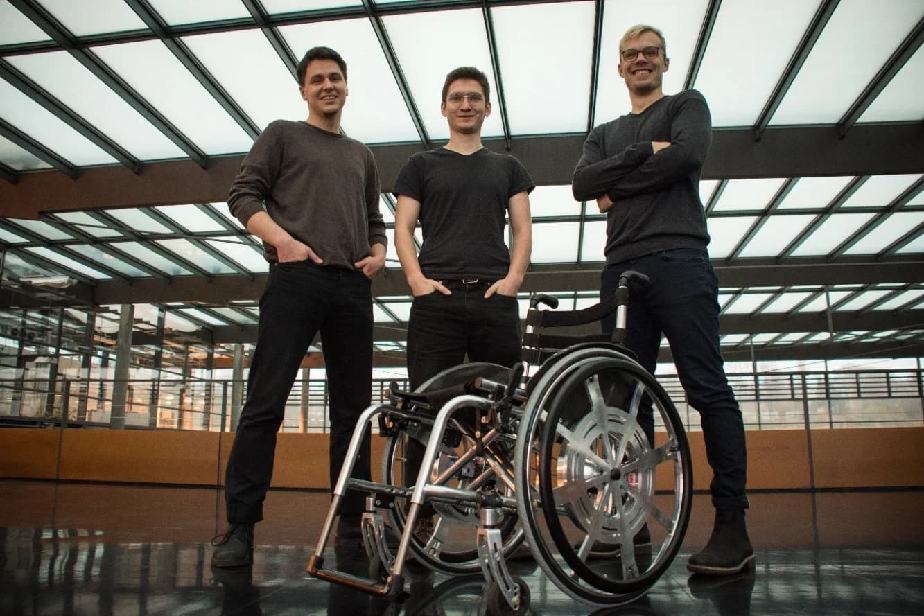
To finish this post, I decided to share with you a rendering of our vision and our team picture with the prototype. From left to right - Alexey, Patrick, Leon.